In This Article
Phase 1: No Power vs. No POST vs. No Display: What's Actually Happening
When a PC powers on—fans spinning, RGB lights lighting up, components receiving power—yet the monitor remains persistently black displaying messages like No Signal Input or entering standby mode, the immediate instinct of many users is to panic and assume a dead processor or catastrophic motherboard failure. Truth is, if fans spin and lights come on, your power supply and motherboard are already doing their job. The real question is where things break down after that.
To troubleshoot efficiently without wasting time or replacing functional components, hardware engineers strictly differentiate between three fundamental failure states:
Completely dead system with zero +5VSB standby rail activity (no motherboard standby LEDs, no fan movement). First verify AC wall power and the PSU rocker switch, then check 24-pin ATX cable seating or reset a tripped PSU short-circuit protection circuit. (If standby LEDs illuminate but the power button triggers no response, check for a disconnected front-panel switch connector on the F_PANEL header.)
Early boot failure. System stalls on either CPU initialization (before RAM is read) or DRAM training (RAM detected but not validated)—these point to different root causes, so isolate CPU socket/power first, then RAM. Fan behavior varies by motherboard: some ramp to 100% failsafe, others idle normally. Power LEDs illuminate, but keyboard lights (NumLock/CapsLock) remain unresponsive since USB host controller initialization hasn't completed.
Late boot failure—or possibly not a boot failure at all. System completes POST and GPU initialization (keyboard lights and disk activity confirm this), but the monitor displays no signal. This usually means either (a) display cable is plugged into motherboard video-out instead of discrete GPU, or (b) GPU seating/PCIe power rail failure. Check cable port routing first before assuming hardware failure.
During cold boot, the power supply asserts PWR_OK once the +12V, +5V, and +3.3V rails are stable. The motherboard's chipset then releases the CPU's RESET# pin, and the CPU begins executing microcode from the BIOS chip—running through DRAM training, PCIe device enumeration, GPU initialization, and boot device selection. A failure at any step—bad register values, poor electrical contact, or unseated pins—stops POST at that exact stage.
Phase 2: Wrong Port, Black Screen: Check Your Cable Routing
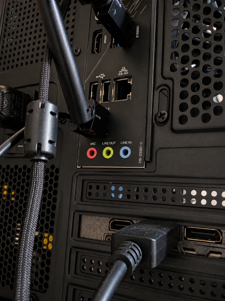
Before touching anything inside the case, confirm your system powers on (fans spinning, motherboard lights on). Cable and port mix-ups are one of the most common causes of a "black screen"—and one of the easiest to fix. If you have a dedicated graphics card, your monitor cable needs to go into a port on the card itself, not the ports on the motherboard's I/O shield.
Critical Connection Rule: Integrated vs Dedicated Video Ports
If your PC has a dedicated graphics card installed in the primary PCIe x16 slot, display cables MUST be plugged directly into the ports on the graphics card, not the ports on the motherboard I/O shield. Plugging into the motherboard ports while using a processor without integrated graphics (such as Intel 'F'-series CPUs like i5-13400F or AMD Ryzen 5 7500F) will result in permanent "No Signal" outputs.
Fix DisplayPort/HDMI Connection Issues
DisplayPort and HDMI use high-speed differential signaling protocols (TMDS, FRL, or DisplayPort Main Link) that require an active Hot Plug Detect (HPD) handshake between the GPU encoder and the monitor scalar chip. If the monitor is powered on after the PC boots, or if DP Multi-Stream Transport (MST) or Display Stream Compression (DSC) gets desynchronized, the GPU may turn off display clock output.
- Perform a Hard Monitor Power Cycle: Unplug the monitor's AC power cable from the wall for 60 seconds (allowing capacitors in the monitor's power board to drain completely), hold the monitor power button for 10 seconds, then reconnect power.
- Test HDMI vs DisplayPort: DisplayPort uses strict HDCP security handshakes. Switch to an HDMI 2.1 cable temporarily to bypass DP link training glitches.
- Manually Force Input Source: Use the monitor's physical OSD joystick/buttons to manually switch input source from 'Auto-Detect' explicitly to 'DisplayPort 1' or 'HDMI 1'.
- Inspect Cable Pin Damage: Check DP cables for bent ground shielding or missing pin 20 power wiring. Never use passive DisplayPort-to-DVI/VGA adapters without active signaling microcontrollers.
Phase 3: Decoding Debug LEDs and POST Codes
Most modern boards from ASUS, MSI, Gigabyte, and ASRock include onboard diagnostic LEDs and a 2-digit display that show exactly where boot is failing—no monitor required.
Reading the EZ Debug LEDs
CPU fail or not detected. Indicates bent LGA socket pins, missing EPS 8-pin 12V power connector, or outdated BIOS microcode for a newly installed CPU.
Memory training failure. DRAM sticks unseated, improper dual-channel slot selection, incompatible XMP/EXPO timings, or oxidation on contacts.
Graphics card initialization failure. GPU not detected in PCIe slot, PCIe latch unclicked, missing 8-pin/12VHPWR GPU power, or bad monitor cable.
POST completed, but boot device (NVMe M.2 SSD / SATA OS drive) not found or corrupted bootloader. Display signal usually present here.
Note: These codes follow ASUS's Q-Code convention. Exact codes and meanings vary by motherboard brand and model—always cross-check against your board's manual before assuming a fix.
| Hex Code | Subsystem | Technical Meaning | Primary Recommended Action |
|---|---|---|---|
| 00 | CPU | No CPU detected, or POST not yet started | Check CPU seating; verify EPS 8-pin power |
| 55 | Memory | RAM not detected or not installed | Reseat RAM one stick at a time in slot A2 |
| 62 / 97 | GPU | Graphics card not initialized / display error | Reseat GPU in PCIe slot; check 12V GPU power |
| A2 | Storage | IDE/SATA/NVMe drive not detected | Check M.2/SATA seating and cable |
| D0–D6 | CPU | CPU-level initialization failure | Often points to a CPU or socket issue—may need RMA |
Phase 4: How to Properly Reseat Your RAM
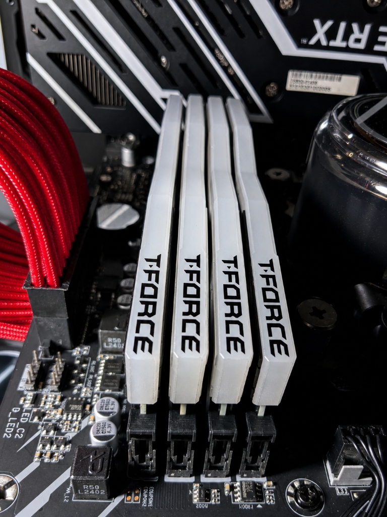
RAM seating issues are one of the most common causes of a failed POST—easy to overlook, easy to fix. High-frequency memory channels run at strict tolerances, so if a module backs out by even half a millimeter or dust enters the DIMM slot, the memory controller in the CPU will halt during memory training.
Step-by-Step RAM Reseating Guide
- 1Power Down & Disconnect AC Power: Shut down system completely. Switch off the PSU toggle switch (set to 'O') and unplug wall power. Wait 15 seconds for motherboard standby capacitors to discharge completely.
- 2Unlatch and Extract All RAM Sticks: Press down on the top and bottom retention latches (or single-sided latch on modern boards) until the RAM module pops upward out of its socket.
- 3Inspect Gold Contact Pins & Slots: Use a soft microfiber cloth or high-purity isopropyl alcohol (99%) to gently wipe the gold edge connectors of the RAM sticks. Use compressed air to blow out any dust trapped inside the motherboard DIMM slots.
- 4Populate Preferred Primary Slot (Slot A2 / DIMM_2): On most 4-slot daisy-chain motherboards, dual-channel setup populatesSlot 2 (A2) and Slot 4 (B2) first (check your motherboard manual, as slot labeling and population order vary by brand).
- 5Apply Firm Vertical Pressure: Align the key notch on the RAM stick with the ridge inside the DIMM slot. Press straight down on both ends simultaneously until you hear an audible, distinct
CLICKfrom the mechanical latches snapping shut. - 6Single-Stick Process of Elimination: If the PC still refuses to boot, test each RAM stick individually in Slot A2. This quickly isolates a single defective RAM stick from functional hardware.
System POST Sequence & Hardware Fault Isolation Flowchart
Use this flowchart to work through the most common causes, in the order most likely to fix your issue.
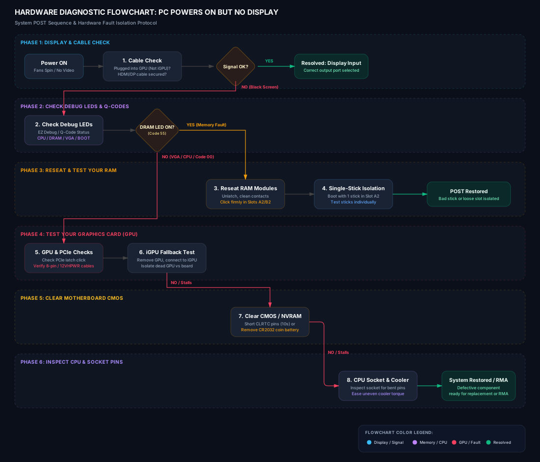
Step-by-Step Flowchart Text Breakdown
A text version of the flowchart above, for anyone who prefers reading over following a diagram.
Phase 1: Display & Cable Check
- Start & Initial Status: System powers ON (fans spin and LEDs light up, but screen remains black).
- Display Cable Routing & Security: Verify display cable (HDMI or DisplayPort) is connected to the dedicated graphics card (GPU) output port rather than the motherboard iGPU port. Ensure connectors are firmly secured.
- Decision Point 1 — Display Signal Restored?
- YES: Problem resolved. Display output signal established.
- NO: Monitor displays "No Signal". Proceed to Phase 2 for hardware diagnostic checks.
Phase 2: Check Debug LEDs & Q-Codes
- Inspect Motherboard EZ Debug LEDs / Q-Code Readout: Observe diagnostic status LEDs (CPU, DRAM, VGA, BOOT) or 2-digit hex code on the motherboard.
- Decision Point 2 — Is Yellow/Amber DRAM LED Solid ON or Q-Code 55 Displayed?
- YES (Memory Fault Detected): Proceed to Phase 3 for RAM module isolation.
- NO (Red CPU LED, White VGA LED, or Code 00): Skip to Phase 4 for GPU & motherboard checks.
Phase 3: Reseat & Test Your RAM
- Reseat System Memory (RAM Modules): Disconnect AC power, unlatch RAM modules, clean gold contact edge connectors, and press firmly back into primary Dual-Channel Slots (Slots A2 and B2) until latches snap shut with a click.
- Single-Stick Isolation Procedure: If POST failure persists, boot with a single RAM stick inserted in Slot A2. Test each stick individually to isolate a bad RAM module vs. a bad memory channel.
Phase 4: Test Your Graphics Card (GPU)
- GPU Seating & Auxiliary Power Cables: Check graphics card in PCIe x16 slot. Ensure retention latch is fully clicked and 8-pin / 12VHPWR power cables are plugged in flush.
- Integrated Graphics (iGPU) Fallback Test: Remove discrete GPU completely. Connect display cable directly to motherboard HDMI/DisplayPort to test if CPU iGPU renders video output.
Phase 5: Clear Motherboard CMOS
- Clear Motherboard CMOS / NVRAM: Short CLRTC / CLR_CMOS jumper pins for 10–15 seconds or remove the CR2032 coin battery for 5 minutes to restore BIOS settings back to factory defaults.
- Decision Point 3 — System Still Refuses to Boot? If POST still fails after clearing CMOS, proceed to Phase 6 for CPU and socket inspection.
Phase 6: Inspect CPU & Socket Pins
- CPU Socket & Thermal Mounting Pressure: Inspect LGA motherboard socket for bent pins under bright lighting. Ease uneven CPU cooler mounting torque to prevent PCB warping.
- Final Resolution: Defective component isolated and ready for replacement or RMA.
Phase 5: Check Your GPU Seating and Power Cables
Heavy graphics cards can sag over time, especially without a support bracket—putting uneven pressure on the PCIe slot and potentially loosening the connection.
PCIe x16 Slot Reseating Procedure
Always disengage the plastic PCIe retention latch at the right edge of the slot before lifting the graphics card. Forcing the GPU out without unlocking the latch can damage the slot's plastic housing or PCB retention hooks.
- Remove IO bracket retaining screws on the chassis expansion slots.
- Press down firmly on the PCIe retention latch to unlock.
- Pull GPU straight outward; inspect x16 edge connector for scratches or debris.
- Reinsert GPU until latch snaps shut with a crisp click.
PSU Auxiliary Power Cables & 12VHPWR
High-draw GPUs require dedicated +12V power rails. Avoid using daisy-chained "pigtail" PCIe cables for GPUs pulling over 225 Watts.
- Use 2 or 3 separate 8-pin PCIe cables directly from the modular power supply.
- If using ATX 3.0 / 3.1 12VHPWR (12+4 pin) cable, ensure connector is flush with ZERO gap to prevent melting and resistance drops.
- Test iGPU fallback: Remove discrete GPU entirely and test display via motherboard HDMI/DP.
Phase 6: Clear CMOS (Reset BIOS to Default)
When BIOS/UEFI settings store invalid memory timings (e.g., an unstable XMP/EXPO profile), incorrect PCIe generation modes (forcing PCIe Gen 4 on a Gen 3 riser cable), or corrupted fast-boot register values, the system will lock up on every subsequent boot attempt. Clearing the CMOS (Complementary Metal-Oxide Semiconductor) non-volatile RAM wipes custom settings back to factory defaults.
Two Methods to Clear Motherboard CMOS
- Turn off PSU and disconnect AC power cord.
- Locate the 2-pin header labeled
CLRTC,CLR_CMOS, orJBAT1near the coin battery. - Touch a metal screwdriver tip across both pins for 10–15 seconds.
- Reconnect power and boot system (allow up to 3 minutes for initial memory retraining).
- Unplug AC power cord from PSU.
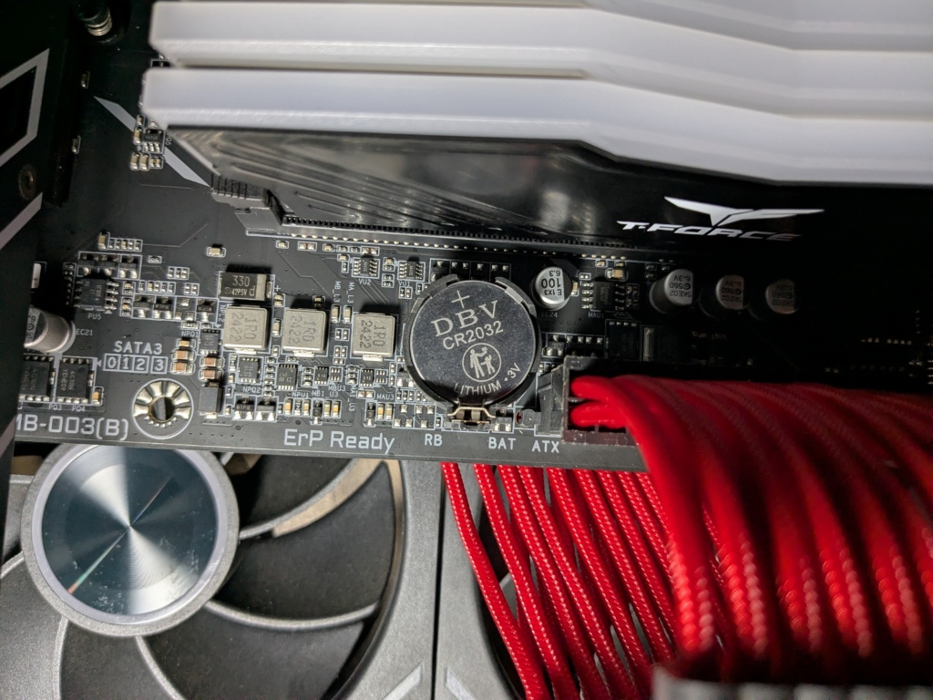
- Locate the silver 3V CR2032 coin battery on the lower half of the motherboard.
- Push the small metal spring catch to release the battery.
- Wait 5 full minutes (or press PC power button 5 times) to drain residual NVRAM voltage, then reinsert battery and power on.
Phase 7: Inspect CPU and Socket Pins
If all memory sticks, GPUs, and CMOS resets fail to produce a display output, the failure is localized to the CPU socket interface or power delivery. Modern Intel (LGA-1700 / LGA-1851) and AMD (LGA-1718 AM5) sockets feature thousands of microscopic spring pins inside the motherboard socket.
- Bent LGA Socket Pins: A single misaligned pin that handles memory channel communication or PCIe lane routing will prevent POST while still allowing CPU cooler fans to spin. Carefully remove the CPU and inspect the pin array under bright light with a magnifying glass.
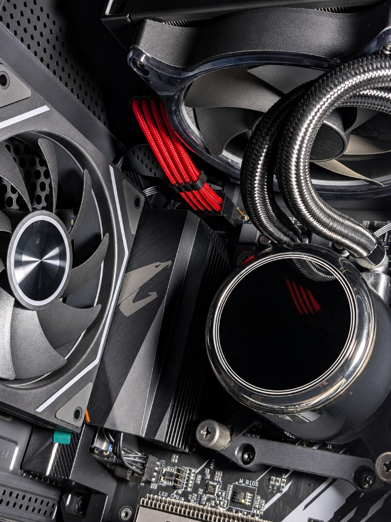
- Uneven CPU Cooler Mounting Pressure: Over-tightening CPU cooler mounting screws (especially custom AIO water blocks or heavy air towers) can cause the motherboard PCB to flex excessively. This flexes the socket and can break electrical contact with the CPU's pads, causing POST failures or memory instability. Back off cooler screws by 1 full turn to equalize mounting torque.
- EPS 8-Pin CPU Power Cables: Ensure the 8-pin (or 4+4 pin) CPU power cable at the top-left corner of the motherboard is fully seated. Do not confuse 8-pin PCIe graphics cables with 8-pin EPS CPU cables.
Phase 8: Hardware Failure Symptoms & Fix Matrix
| Primary Physical Symptom | Root Cause Hardware Component | Isolation Action Item | Likelihood |
|---|---|---|---|
| Fans spin, monitor power LED blinks, white VGA debug LED on | GPU / DisplayPort Cable | Reseat GPU in PCIe x16 slot; switch DP cable to HDMI port. | Very Common |
| Fans spin at 100% max speed, amber/yellow DRAM LED solid on | DRAM Memory Stick / Slot A2 | Reseat RAM modules firmly into Slot A2/B2 until latch clicks. | Most Common |
| System turns on, red CPU LED stays on, zero keyboard LED power | CPU / Outdated BIOS Version | Perform USB BIOS Flashback to update microcode for new CPU. | Common |
| PC turns on for 3 seconds then restarts in an infinite boot loop | Corrupted CMOS / Unstable XMP | Short CLRTC pins for 15 seconds to restore stock BIOS defaults. | Common |
| No display output after installing a new high-wattage graphics card | Power Supply (PSU) PCIe Rails | Use 2 dedicated 8-pin PCIe power cables instead of a single daisy chain. | Very Common |
Still Experiencing No Display Issues?
Tried all 8 phases and still staring at a blank screen? Feel free to contact me directly, and I'll do my best to help you narrow down the hardware issue.